PACKAGE CONVEYANCE STABILITY PROJECT
Dematic’s new model of conveyor is called the 9570 unit and is a high speed live roller conveyor. This new model is designed to transport packages while maintaining a high speed of at least 3 m/s. While this new unit was being tested at the Dematic Tech center, it was discovered that when small and light weight packages get diverted onto the unit, they experience turbulence which causes the packages to spin or flip over. Orientation of packages on conveyor is extremely important for scanning purposes. In order to fix this problem, the problem first had to be replicated. A piece of the 9570 unit was sent to Central Washington University (CWU) to be reconstructed and manipulated. Once the conveyor was assembled, initial testing was done to recreate the same problem. However, the behavior seen in the videos could not be consistently replicated. Originally it was thought that the speed the small box was being launched onto the conveyor would correlate with turbulence. However the testing proved no direct correlation between turbulence and launching speed.The next step would be to test how the speed of the cross belt could affect the turbulence of small packages.


CONSTRUCTION
9570 CONVEYOR
Setting up the conveyor came with a lot of road blocks. First, the drawings provided by Dematic explained how to install each component but failed to show where each component went on the conveyor. A fellow employer of Dematic was able to provide images from underneath a 9570 unit from the tech center that could be replicated. A new belt was ordered because Dematic only provided one that was the wrong size. Lastly, saw horses were ordered to place the conveyor on because there were no supports provided either.
LAUNCHER
The first device built was the launcher that will simulate the packages being diverted off the cross-belt onto the 9570 unit. The launcher consists of three pieces of wood, wooden dowels, surgical tubing, and screw eyes. The wood was utilized from scrap wood from the woodshop and so were the wooden dowels. The surgical tubing and screw eyes were ordered from amazon. A band saw was used to trim the edges giving the final length of the board to be 21.5.” It is 14” wide and 1.5” thick. The two guides were cut to 18” x 3” x 0.85.” Two 0.25” diameter holes were drilled using a drill press in the wood shop. They were drilled 1.5” in from the width and 3” in from each end. The piece of wood for the launching surface was marked for where to drills so that the guide piece could be moved in order to guide the different package sizes. Some of the holes were too close when the packages were placed in between the guides. It would have caused friction to the packages so where the guides were clamped had to be adjusted. The holes on the launching surface were drilled through the holes on the guides to guarantee proper alignment.


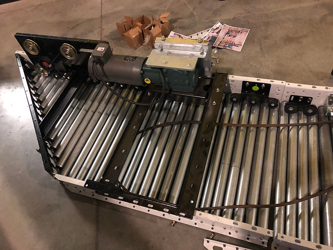
FLIPPED CONVEYOR
After the belt was mounted onto the 9570 unit the conveyor was ready to be flipped onto the saw horses and hooked up to power.
ANGLE IRON
The design of the angle bracket was changed in order to better adjust how/where the packages are being launched onto the conveyor. Originally, the bracket was just going to be bolted to the center of the conveyor but then that would not be easily manipulated. Three different sets of holes were drilled into the conveyor to launch the packages at three different spots. The holes in the angle bracket were milled to slots to adjust the height and angle of how the packages are diverted.
 |  |  |
|---|---|---|
 |
Conveyor
This video includes the completed conveyor. The new belt and saw horses had arrived. The belt was mounted under the conveyor and then the conveyor was flipped to rest onto the saw horses. The launcher is completed and attached onto the end of the conveyor. The conveyor was then hooked up to power and can be seen running in the testing video below.

LAUNCHER REDONE
After failing to correctly and consistently replicate the problem it was realized that it was necessary to change the angle on the launcher to better replicate the cross belt from the tech center that the boxes are being launched from. The analysis showed that boxes should be coming into contact with the rollers at an angle of 40 degree. New holes needed be drilled into the launcher so that the guide boards could be res-positioned. Luckily the launchers simple design allowed for an easy manufacturing fix for this issue.